1.8 Overview of the Complete CCD Process
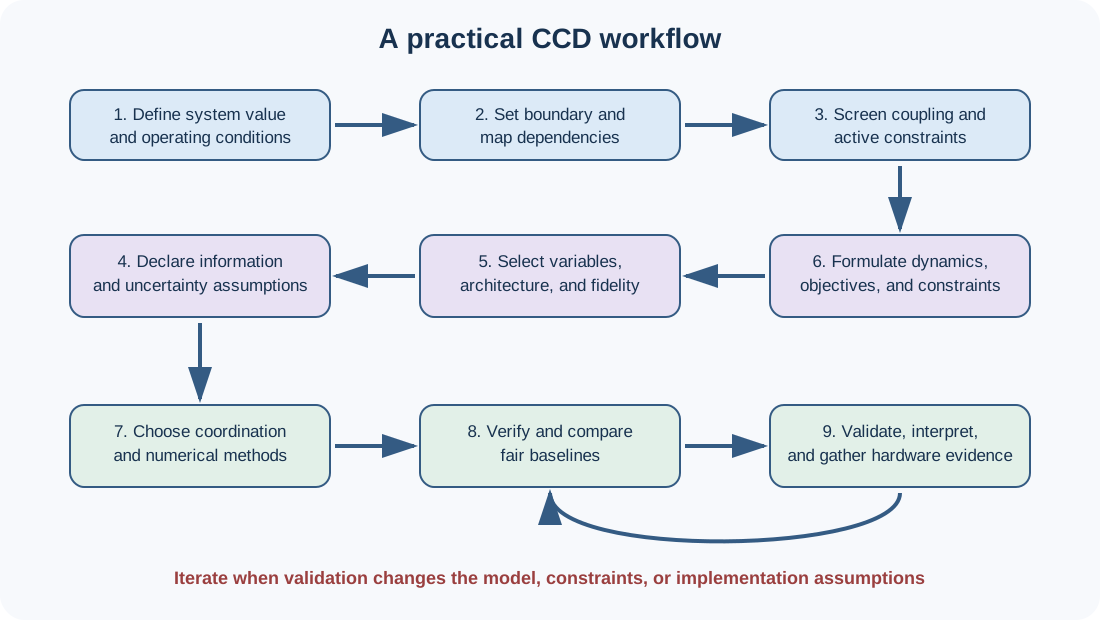
An end-to-end workflow
A trustworthy CCD study is a sequence of engineering arguments, not merely a solver call.
Define system value. State the mission, operating conditions, stakeholders, and system-level metrics.
Choose the boundary. Include physical, control, sensing, actuation, information, energy, and thermal effects that can change the decision.
Map dependencies. Connect every candidate variable to dynamics, objectives, constraints, and other disciplines.
Screen coupling. Retune controls across candidate plants and inspect active constraints and sensitivities.
Declare information assumptions. Separate full preview, limited prediction, state feedback, and noisy estimated feedback.
Select variables and architecture. Distinguish continuous parameters, discrete choices, controller parameters, and trajectories.
Formulate dynamics and constraints. Include saturation, rates, path constraints, uncertainty, and failure requirements.
Choose coordination and numerical methods. Sequential, nested, simultaneous, or hybrid; simulation-based or direct transcription.
Verify the computation. Check derivatives, scaling, convergence, mesh or time-step refinement, and multiple initial guesses.
Compare fair baselines. Retune every controller and apply identical requirements.
Validate beyond the optimization model. Use unoptimized conditions, higher-fidelity simulation, uncertainty, and ultimately hardware.
Interpret and communicate. Explain why the design changed and whether the gain survives implementation.
First quarter-car formulation
With body displacement , wheel displacement , and road input , a simple active quarter car is
A first CCD problem can choose and feedback gains to minimize
subject to closed-loop stability, , suspension travel, tire deflection, and bounds on the physical variables.
Implementation pseudocode
define plant variables, controller variables, and operating scenarios
for each candidate design requested by the optimizer:
    assemble the plant model from physical variables
    construct or tune the controller
    simulate every required scenario
    evaluate system objective and constraints
verify derivatives and numerical convergence
solve from multiple initial designs
retune and evaluate sequential baselines
validate selected designs using higher-fidelity and uncertain models
Common mistakes
Chapter summary
Control co-design treats physical and control decisions as parts of one dynamic-system design problem. Its value comes from preserving coupled design freedom, discovering performance or feasibility synergies, and making implementation assumptions explicit. CCD includes control-inspired invention, formal co-optimization, and model/data-based co-simulation. It is most useful near coupled limits and least useful when interfaces are weak, decisions are frozen, or modeling uncertainty overwhelms the predicted benefit.
Exercises
Derive a state-space model for the quarter-car equations using . Identify every matrix entry affected by and .
Give one example in which increasing actuator authority changes the optimal physical design and one in which it does not.
Construct a two-variable objective for a DC motor and gear train in which gear ratio and feedback gain are coupled. State realistic constraints.
Compare control-inspired design, co-optimization, and co-simulation for a flexible robotic arm. What would each perspective contribute?
Design a fair numerical experiment that tests whether a sequential suspension design is within 2% of the integrated optimum.
Explain why an OLOC-optimal plant may not be optimal under noisy, delayed feedback.
Apply the qualitative value screen from Section 1.6 to a wind turbine, microgrid, or assistive robot.
Identify three pieces of evidence required before an organization should adopt the CCD result in hardware.
Open research question
Can a computationally inexpensive, model-agnostic diagnostic reliably predict the value of CCD before a full co-design optimization is solved?
Sources and further reading
M. Garcia-Sanz, “Control Co-Design: An Engineering Game Changer,” Advanced Control for Applications, vol. 1, e18, 2019.
J. T. Allison and D. R. Herber, “Multidisciplinary Design Optimization of Dynamic Engineering Systems,” AIAA Journal, vol. 52, no. 3, pp. 691–710, 2014.
D. R. Herber and J. T. Allison, “Nested and Simultaneous Solution Strategies for General Combined Plant and Control Design Problems,” Journal of Mechanical Design, 2019.