4.11 Standard Notation Used Throughout the Course
Core symbols
| Symbol | Meaning | Typical dependence |
|---|---|---|
| time, initial time, final time | independent variable | |
| time-independent plant variables | geometry, materials, ratings | |
| time-independent controller parameters | gains, weights, horizons | |
| architecture variables | binary, integer, categorical, placement | |
| differential state trajectory | governed by | |
| algebraic-variable trajectory | governed by | |
| commanded or delivered control input | optimized or generated by | |
| prescribed environment, reference, or disturbance | not selected in the nominal problem | |
| measured output | sensor model plus noise | |
| performance output | used in objectives or constraints | |
| uncertain quantities | parameters, inputs, noise, model error | |
| running objective integrand | accumulated over time | |
| terminal or endpoint objective | evaluated at boundaries | |
| inequality constraints | feasible when | |
| equality and algebraic constraints | feasible when equal to zero | |
| boundary constraints | initial, final, or linkage conditions | |
| control policy | maps available information to | |
| controller information available at time | measurements, estimates, preview |
Conventions
Boldface is omitted when dimensions are clear. A superscript denotes an optimized value, not necessarily a proven global optimum. Bounds use superscripts and . A hat denotes an estimate, a tilde may denote an uncertain quantity, and a subscript denotes a discrete mesh or sample index. Scenario indices use .
The symbols are stable, but their dimensions are problem dependent. For example, may be scalar motor voltage or a vector of turbine pitch and torque commands. Every application must state units, scaling, sign conventions, and whether a control variable is commanded or delivered.
Chapter summary
The unified formulation separates time-independent decisions, time-dependent trajectories, prescribed data, uncertainty, performance, dynamics, and feasibility. Plant and control decisions interact through shared equations and limits. Architecture changes what components and information exist. A complete CCD description also reports control representation, information availability, coordination, model fidelity, uncertainty, algorithm, and validation level.
Common mistakes
using the same symbol for a plant decision and a time-varying state;
optimizing a state or algebraic value without enforcing its governing equation;
assuming full state or disturbance knowledge without a sensor, estimator, or preview model;
confusing command, actuator output, and generalized plant input;
checking path constraints only at coarse sample points;
comparing architectures under different objectives or information; and
calling an uncertain variable deterministic merely because one nominal value was simulated.
Exercises
Write the complete deterministic CCD formulation for the positioner using PD gains and a selectable velocity sensor.
Replace PD gains with an optimized voltage trajectory and list the information assumption that changes.
Add uncertain payload mass and formulate expected energy plus a terminal-error chance constraint.
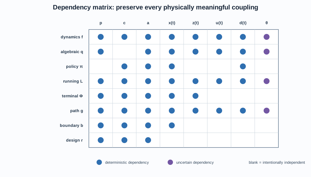
Construct a dependency matrix for link length, motor rating, gear ratio, sensors, states, control, objectives, and constraints.
Classify your formulation using every axis of the master CCD taxonomy.
Principal sources
The formulation-to-solution organization and graphical vocabulary follow the integrative wind-turbine CCD review by Bayat and coauthors. The general dynamic-system formulation follows Allison and Herber’s dynamic-MDO and plant-control co-design work. The uncertainty notation anticipates the UCCD taxonomy developed by Azad and Herber. All diagrams here are original course figures.
Open research question
Can a machine-readable CCD problem specification preserve physical meaning, information assumptions, architecture logic, uncertainty, and solver interfaces well enough to make formulations portable across domains and software ecosystems?