An ideal model applies uc(t) directly to the plant. A real actuator has internal dynamics and limits. A first-order model is
τau˙+u=uc,
with constraints
umin≤u≤umax,u˙min≤u˙≤u˙max.
Electrical current, voltage, hydraulic flow, motor speed, temperature, duty cycle, and stored energy may impose additional constraints. The actuator rating is often a plant design variable; the achievable control trajectory depends on it.
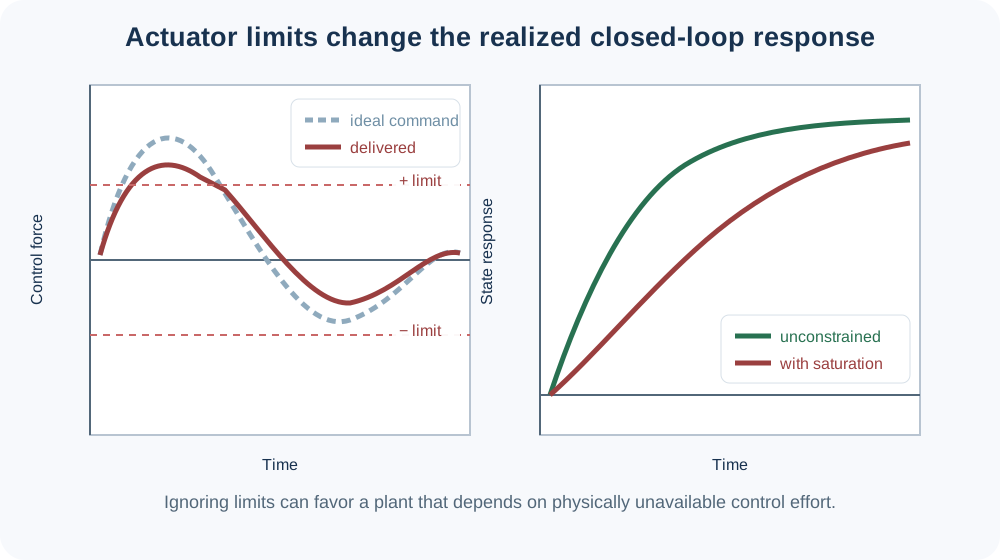
When the controller saturates, the closed loop is nonlinear and the assumed pole locations no longer describe the response. Integral action may wind up. An optimizer that ignores saturation can reduce passive capability and rely on control effort that hardware cannot deliver.
Including only a large penalty on u2 is not equivalent to enforcing a hard force limit. A penalty discourages effort when convenient; a constraint prohibits an impossible command.
Actuator bandwidth must cover useful control frequencies, but extending bandwidth into uncertain flexible modes can reduce robustness. Collocated actuator-sensor pairs often have favorable passivity properties, while noncollocated arrangements can introduce difficult zeros and phase loss.
For a beam, a high-force slow actuator may control rigid motion but not vibration. A smaller piezoelectric actuator may address high-frequency modes but provide little stroke. Architecture and placement may require multiple actuator technologies.
Anti-windup logic, reference governors, MPC, and command shaping can manage limits, but they cannot create unavailable authority. CCD should include the intended limit-handling strategy during evaluation because different strategies can change the preferred passive design and actuator rating.