Actively Controlled Engineering Systems
The physical system is only part of the design
An engineering system is active when it senses its condition or environment and uses an actuator to modify its behavior. A useful system description contains five interacting elements:
Physical plant: the object or process being controlled, such as a vehicle suspension, wind turbine, robotic arm, building, aircraft, or energy converter.
Sensors: devices that measure position, velocity, strain, temperature, pressure, acceleration, current, or other quantities.
Controller: logic that uses measurements, models, references, and design parameters to determine a command.
Actuators: devices that convert the command into physical action such as force, torque, heat flow, voltage, valve position, or blade pitch.
Environment: external conditions and disturbances such as road roughness, wind, waves, payload changes, and uncertain loads.
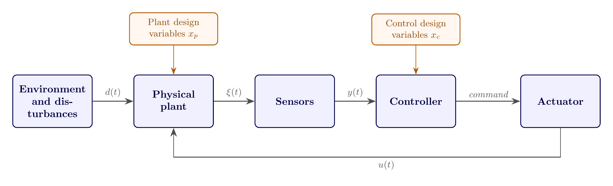
A generic actively controlled engineering system. Every block contributes to the behavior of the complete system.
The controller is not an isolated software object. It acts through a physical actuator, receives imperfect measurements from physical sensors, and operates on a plant exposed to disturbances. Sensor bandwidth, actuator limits, power availability, computation, and plant dynamics therefore belong to the same engineering story.
Plant and control design variables
Engineers choose quantities called design variables. Once a system’s architecture is fixed—an assumption examined critically later in this section—two broad groups of variables remain to be chosen.
Plant design variables describe the physical system. Examples include:
geometry, shape, and material;
mass, inertia, stiffness, and damping;
gear ratio, generator rating, battery capacity, and actuator size; and
sensor or actuator placement when it changes the physical system.
Control design variables describe how control action is generated. Examples include:
PID or state-feedback gains;
estimator and filter parameters;
sampling time and model-predictive-control horizon;
parameters of a control policy; and
an entire control trajectory in open-loop optimal control.
The boundary is sometimes context dependent. A sensor can be viewed as hardware, an information-architecture choice, or both. The label is less important than representing how the decision changes dynamics, information, performance, cost, or constraints.
A third design domain: architecture
Plant and control variables both presume that which components exist and how they connect has already been decided. That decision is itself a design choice, and a consequential one: architecture is the set of elements contained in a system and the relationships among them—which components are present, of what type, and how they are connected. Architecture design is normally a discrete decision (which components, in which arrangement), in contrast to the continuous sizing decisions of and the trajectory or gain decisions of .
A pick-and-place robotic manipulator makes the distinction concrete. Before any link length or joint controller can be chosen, a designer must decide the manipulator’s architecture: how many links and joints it has, how they are connected (series or parallel kinematic chains), which joints carry an actuator and are therefore active, and whether extra structural components—an end-effector plate, a brace—are included. A two-link serial arm, a three-link serial arm, and a four-link parallel arm performing the identical pick-and-place task are three different architectures, each admitting its own plant variables (a two-link arm has two link-length variables; a four-link arm has four) and its own control problem (a different number of actuated joints to command). Only once an architecture is fixed do “the plant variables” and “the control variables” refer to a well-defined, finite list.
Architecture, plant, and control decisions are often assigned to different engineers or made at different times—an organizational habit rather than a technical necessity—and the same practical hazard identified for sequential plant-then-control design applies one level up: fixing an architecture before plant and control possibilities under alternative architectures have been explored can foreclose the best system-level design just as surely as fixing a plant before its controller does. A hybrid-electric vehicle’s series, parallel, and power-split drivetrain architectures are a common example: each admits its own plant sizing and control problem, and comparing architectures fairly requires solving a genuine co-design problem within each one rather than reusing a plant or controller tuned for a different architecture.
Decisions also migrate between domains depending on how much a designer is willing to model. A structural topology decision can be relaxed into a continuous plant variable (density-based structural optimization treats “is material present here” as a continuous variable rather than a discrete choice); a genuinely architectural decision—which power-take-off hardware a wave energy converter uses—is sometimes simplified into an assumed control structure so that standard control-design tools apply; and, in the sequential workflows criticized throughout this chapter, a control decision is sometimes reduced to tuning only the passive plant, leaving the feedback controller out of the problem entirely. None of these simplifications is wrong by itself; each one trades scope for tractability, and a CCD study should be explicit about which domain’s flexibility it has traded away.
States, outputs, controls, and disturbances
Let the state, control input, disturbance, and output be
A general state-space model is
The physical design appears inside the dynamic model. Changing a mass, dimension, stiffness, aerodynamic shape, or gear ratio changes the equations of motion and can therefore change which controller is best.