Chapter 8: Plant, Controller, Sensor, and Actuator Architecture Co-Design
Designing what components exist and how they are connected
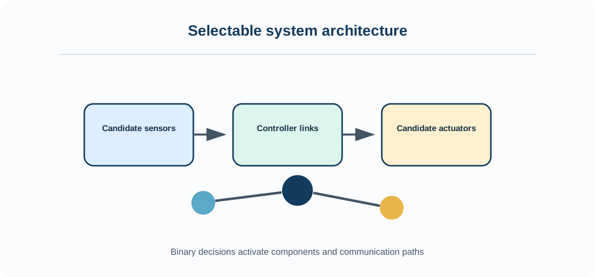
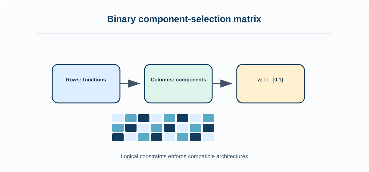
Architecture co-design decides which components, connections, measurements, and control channels exist. Parameter optimization then chooses values within each logically consistent architecture.
Learning objectives
After completing this chapter, you should be able to:
explain and apply physical topology;
explain and apply actuator set;
explain and apply sensor set;
explain and apply information network;
formulate and verify the chapter methods on sensor and actuator selection for a flexible structure, suspension alternatives, and hybrid-powertrain topology.
Mathematical lens
The recurring quantities are , continuous , and controller design :
Running example
The recurring example is sensor and actuator selection for a flexible structure, suspension alternatives, and hybrid-powertrain topology. Retaining one system prevents apparent improvements from being caused by changed physics, information, loads, or metrics.
Recommended workflow
generate architectures.
enforce logic.
optimize parameters.
test faults.
compare value.
Chapter map
Parameter Design Versus Architecture Design
Plant Topology Decisions
Actuator Sizing and Placement
Sensor Selection and Placement
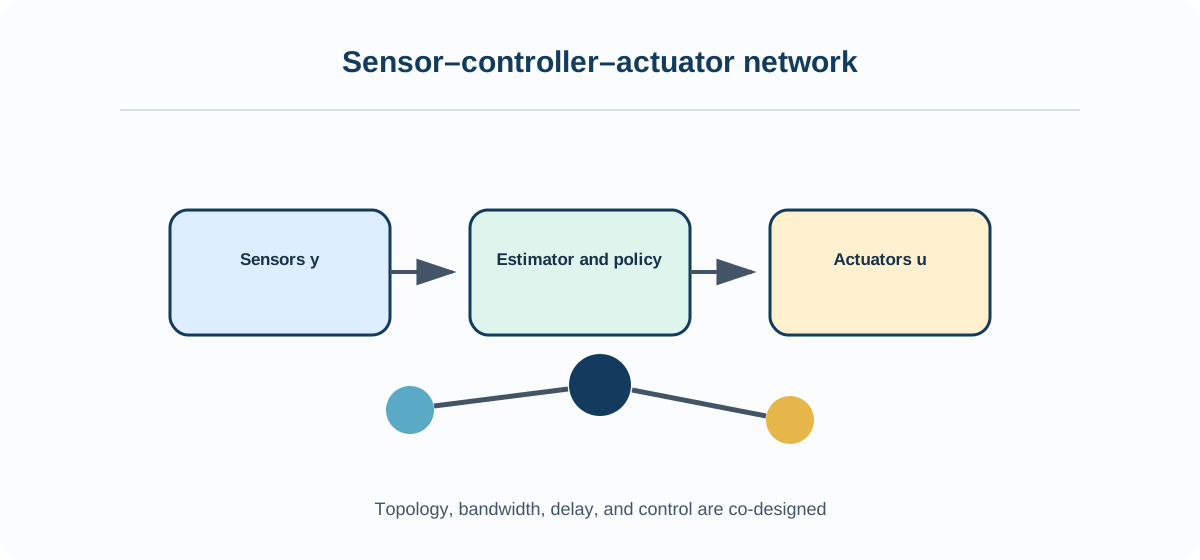
Communication and Information-Flow Architecture
Redundancy and Fault Tolerance
Binary and Integer Design Variables
Mixed-Integer CCD
Controller-Order Selection
Architecture–Parameter–Control Optimization